design of knuckle joint video
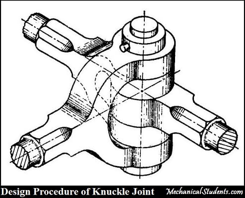
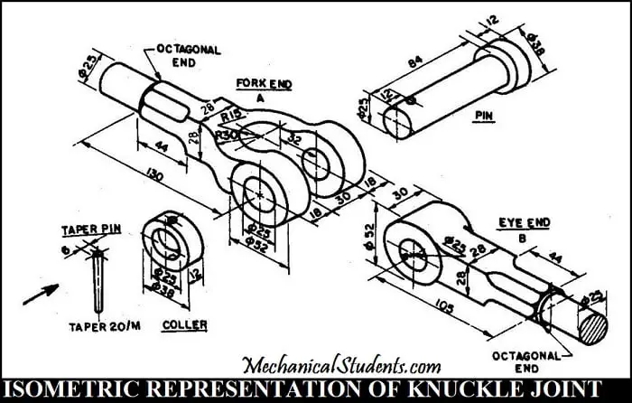
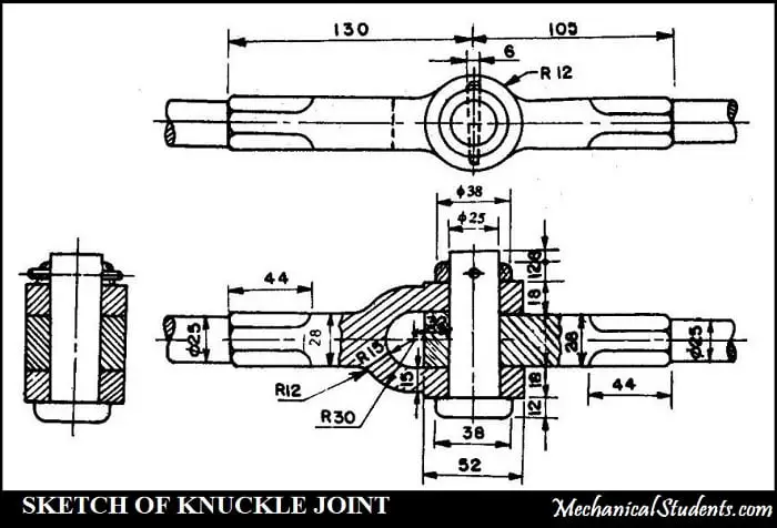
A Knuckle Joint is used for the application of the Tie rod joint of jib crane or Tension link in the structure of the bridge. In this article, I am going to present a detailed explanation of the design procedure for Knuckle Joint and Cotter Joint. Let's see the definition of Knuckle Joint... When there is a requirement of an angular moment or a small amount of flexibility, the Knuckle joint is used. A knuckle joint is used to connect two rods that are under a tensile load. The Diagram of Knuckle Joint is shown below. The Assembly of Knuckle Joint consists of 3 parts. They are There is a single eye at one end of the rod and Double-eye on the end of another rod which is also called Fork End. Both, Single eye and Double-eye (Fork End) are connected employing a Knuckle pin inserted through the eye. One end of the knuckle pin has a head section and the other end is tapered along with a hole on its surface for the insertion of Taper pin after assembly as shown in the above figure. The cross-section at the ends of the rod are of octagonal and is designed for the purpose of Gripping. The pin is used to hold one eye end of a rod and the fork end of the other rod firmly. Now, the Coller is placed exactly on the surface of the rod having a hole such that the Taper pin can be inserted into it. Thus the assembly of Knuckle Joint can be done. Lets see the drawing of Knuckle joint in Orthographic Representation. The Drawing of Knuckle joint in the form of 2D sketch i.e. Front View, Top View, and Side View is shown below. The failures of Knuckle Joint are as follows. The applications of Knuckle Joint is as follows. The assembly diagram of knuckle joint is as shown in fig. The dimension of knuckle joint are: 4. Design of fork (double eye): The detailed explanation for the Design Procedure for Knuckle Joint is shown below in the form of video. I hope you have understood well with the help of above video. Let's discuss about Cotter Joint too... Cotter's joint is widely used to connect the piston rod and crosshead of a steam engine, as a joint between the piston rod and the tailor pump rod, foundation bolt, etc. Cotter's joint is used to connect two rods subjected to compressive or axial tensile loads. It is not at all suitable to connect rotating shafts which transmit torque. The Diagram of Cotter Joint is shown below. The Cotter joint Assembly or the Parts of Cotter Joint are as follows. The parts of Cotter joint are The explanation for the parts of Cotter Joint are as follows. The socket is the female part of the Cotter joint which has a hole at the center such that the spigot can fit into it. It also has a rectangular slot on its surface such that the cotter can pass through it. The spigot is the male part of the Cotter joint which has also a rectangular slot on its surface such that the cotter can pass through it. The Spigot is inserted into the socket such that the rectangular slots of both (spigot and Socket) can meet with each other and then the Cotter pin is inserted into it for fixing it firmly. The Cotter Joint Failures are as follows. The applications of Cotter Joint are as follows. The Advantages of Cotter Joint are as follows. The remaining part for the design procedure of a cotter joint is presented in the form of a video which is shown below. This is the complete explanation of the Design Procedure for Cotter Joint and Knuckle Joint which is shown in a detailed manner. If you have any doubts, feel free to ask from the comments section. Please Share and Like this blog with the whole world so that it can reach to many. The knuckle joint is used to connect two rods under tensile load. knuckle joints are biaxial. More Resources: Knuckle Joint Definition:
Knuckle Joint Diagram:
Knuckle Joint Assembly or Parts of Knuckle Joint:
Knuckle Joint Drawing:
Knuckle Joint Failure:
Applications of Knuckle Joint:
Design Procedure for Knuckle Joint is Made to Calculate:
Specifications for Knuckle Joint:
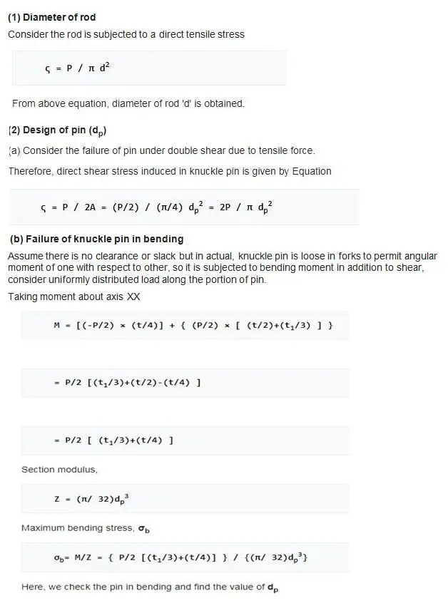
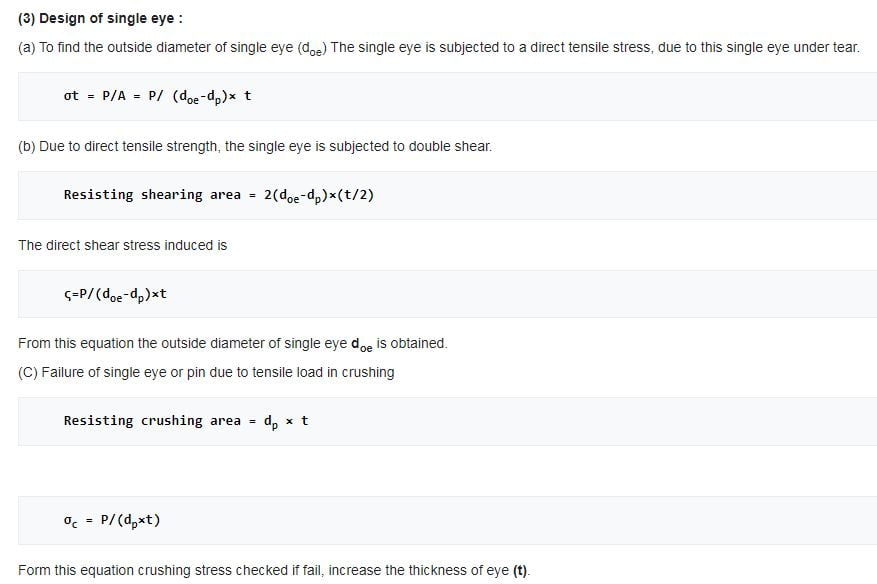
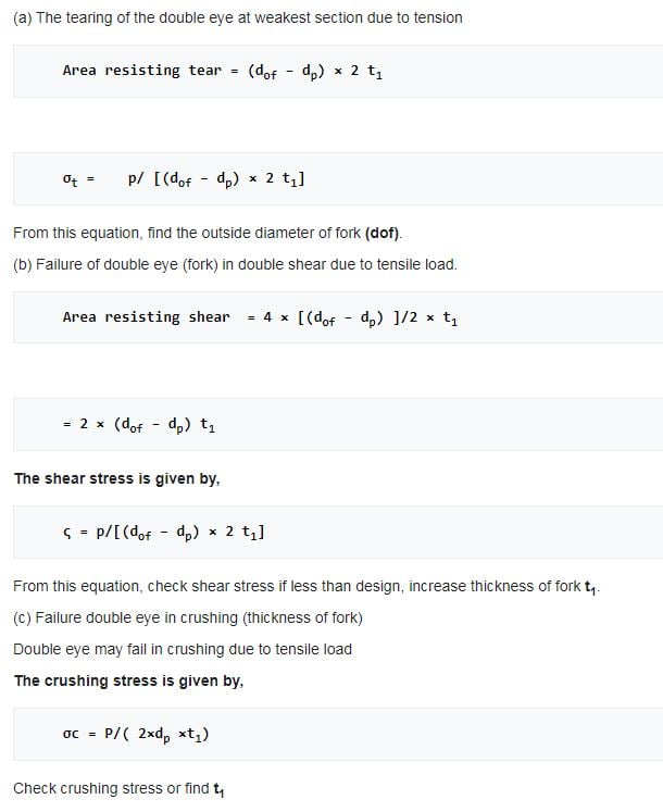
Cotter Joint:
Cotter Joint Definition:
Cotter Joint Diagram:
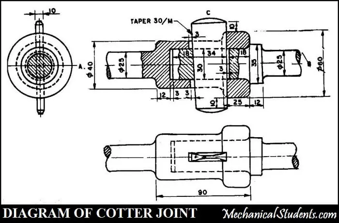
Cotter Joint Assembly:
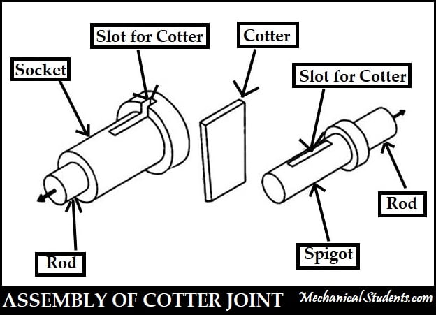
Cotter Joint Parts:
Socket:
Spigot:
Cotter Pin:
Cotter Joint Failure:
Design Procedure for Cotter Joint is Made to Calculate:
Applications of Cotter Joint:
Advantages of Cotter Joint:
Some FAQs on Cotter Joint and Knuckle Joint:
Where is the knuckle joint used?
What type of joint is knuckle?
Hotchkiss Drive & Torque Tube Drive References [External Links]:
design of knuckle joint video
Source: https://mechanicalenotes.com/design-procedure-for-knuckle-joint-and-cotter-joint/
Posted by: hancockmanote.blogspot.com

0 Response to "design of knuckle joint video"
Post a Comment